LensTip.com

Articles

Everything you always wanted to know about the semi-transparent mirror technology (but were afraid to ask)

19 January 2015
Szymon Starczewski

5. Test of the Sony A99 mirror

Build quality

Everything you always wanted to know about the semi-transparent mirror technology (but were afraid to ask) - Test of the Sony A99 mirror

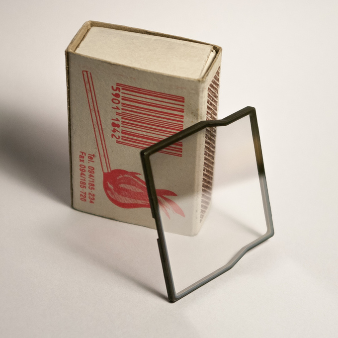
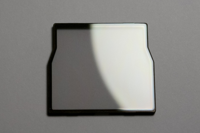
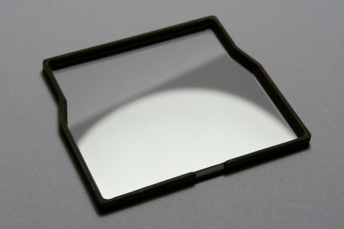
A stressed film mirror is glued into a frame. Similar technique is used with adaptive optics – mirrors which can change their shape. It means that indeed such a method is applied in a production process of technologically most advanced mirrors.

Everything you always wanted to know about the semi-transparent mirror technology (but were afraid to ask) - Test of the Sony A99 mirror


Please Support Us

If you enjoy our reviews and articles, and you want us to continue our work please, support our website by donating through PayPal. The funds are going to be used for paying our editorial team, renting servers, and equipping our testing studio; only that way we will be able to continue providing you interesting content for free.

- - - - - - - - - - - - - - - - - advertisement - - - - - - - - - - - - - - - - -

- - - - - - - - - - - - - - - - - - - - - - - - - - - - - - - - - - - - - - - - - - - - - - - -
Everything you always wanted to know about the semi-transparent mirror technology (but were afraid to ask) - Test of the Sony A99 mirror

Still it doesn’t mean the camera comes with a bit of astronomical optics inside. Let’s have a look at the flatness of the surface.

Everything you always wanted to know about the semi-transparent mirror technology (but were afraid to ask) - Test of the Sony A99 mirror
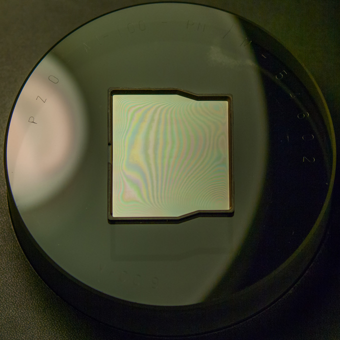
The mirror placed on the interference optical flat test

In order to perform that test it was necessary to cut off the excess of film which stuck out outsider the frame. The tested flat surface shows a homogeneous shade of one colour or parallel, equidistant, straight fringes with constant period. You can notice a huge deviation from flatness (employing, of course, optical quality criteria). The stretched film should be very even unless there are differences in density, thickness or the frame is not flat and circular. Indeed it is not. You could say such a flawed mirror is not suitable for optical use but still you must remember that the reflected light is not used for imaging. The result has just an informative value and should be treated as such.

Everything you always wanted to know about the semi-transparent mirror technology (but were afraid to ask) - Test of the Sony A99 mirror

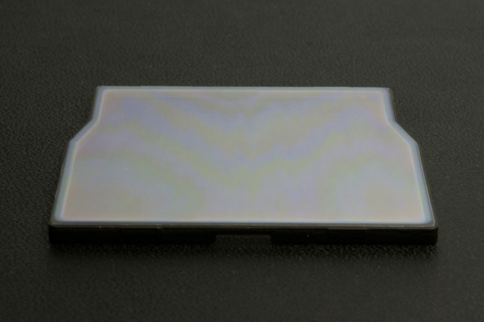
If you look closely at it under a fluorescent lamp you can notice interference fringes which are created in thin layers, covering the mirror, or in the film itself. There are 4 stripes which means an unevenness of about 1 µm, so circa 3% of the total thickness. In the transmission test it became clear that such a homogeneity result is completely sufficient; still it influences the resolution in some range for sure, adding an effect which in a case of a perfect system, presented in the previous chapter, wasn’t taken into account.

The mirror looks solid and should withstand several cleanings; its optical quality is good enough to make it a useful tool of the focusing mechanism. Still you should keep in mind the fact you deal here with a piece of very thin film, easy to destroy accidentally.

Transmission

During our test we found out that the absorption losses in the mirror are negligible. The amount of reflected light can be presented as the following formula: R=I-T, where I is the intensity of incident light and T - intensity of reflected light. It’s enough to present the results of mirror transmission measurements - let’s start from the perpendicular direction.
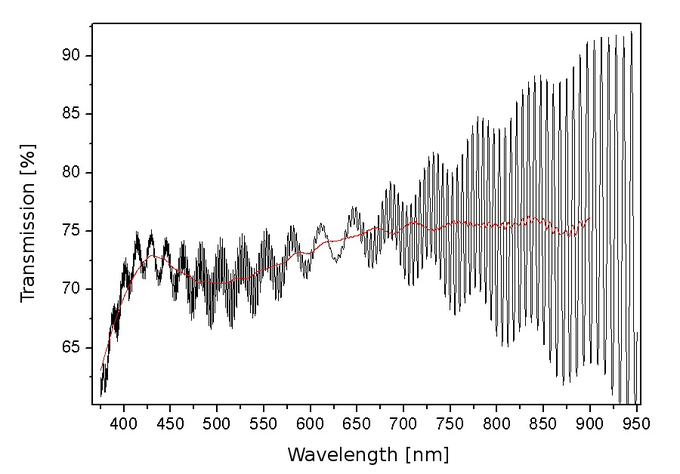
Everything you always wanted to know about the semi-transparent mirror technology (but were afraid to ask) - Test of the Sony A99 mirror
Transmission in case of the perpendicular direction

You can observe a beautiful example of multi-beam interference. Two sets of fringes overlapping each other mean a distinct difference in indexes of refraction between base and vapour deposited dielectric layers. In spite of appearances you shouldn’t worry about it. The interference stripes change their positions depending on the light incidence angle so the sensor gets an averaged light, close to the red curve shown on the graph. We tried to reconstruct any possible effects connected to such fringed characteristics but we failed.

Still it can be noticed that the light passing through the mirror doesn’t have a neutral colour anymore. The detector gathers the biggest amount of red light, then comes blue and finally green-yellow.

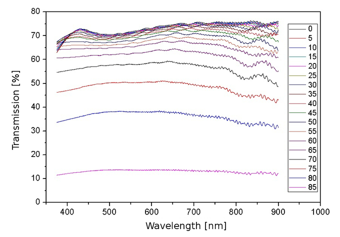
The transmission measurement was performed for different angles of incidence every 5 degrees. The results are presented in the raw form and after averaging out.
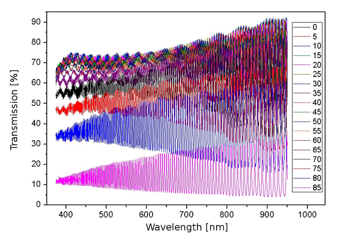
Everything you always wanted to know about the semi-transparent mirror technology (but were afraid to ask) - Test of the Sony A99 mirror
Transmission as a function of wavelength for different angles - raw values

Everything you always wanted to know about the semi-transparent mirror technology (but were afraid to ask) - Test of the Sony A99 mirror
Transmission as a function of wavelength for different angles - averaged values


The distribution of transmission across the spectrum in the range from 400 to 700 nm so in places where the sensor is most sensitive, is contained in the 5-10% range. The faster the lens the more averaged the final result is. That regularity stems from the fact that image points are created by beams which come from different directions so their angles of incidence are averaged on the mirror.

The relationship between the transmission and angle of incidence was determined by using the averaged transmission in the 380-780 nm range so covering the whole visible spectrum.
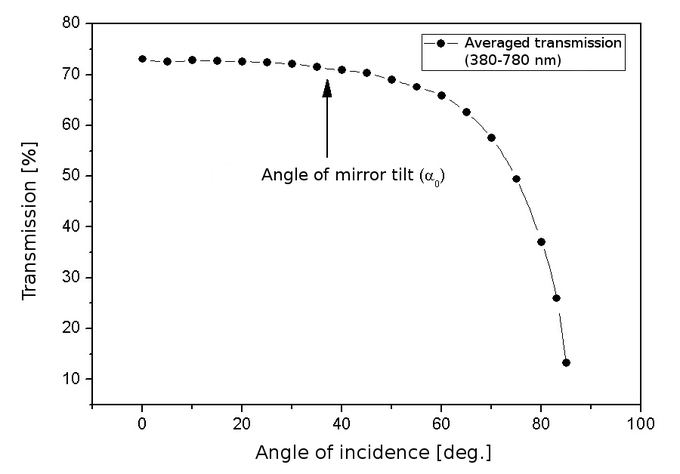
Everything you always wanted to know about the semi-transparent mirror technology (but were afraid to ask) - Test of the Sony A99 mirror
The relationship between the transmission and angle of incidence


The mirror let 70-75% of light pass through in a wide range of angles. The brightness loss connected to big angles is noticeable only with fast lenses where it most probably remains negligible anyway due to a mix a lot of beams which fall under different angles. The effect will be averaged like in the case of spectral fringes. For typical lenses the brightness differences can be contained in a 10% range, a value easy to hide permanently in the electronics of the camera.

Disturbance of wavefront – interferometric measurement

Let’s fire big cannons now. Optical interferometric measurements are among the most precise so in order to assess the perturbations introduced by the mirror to the beam of light passing through it we used the Mach-Zehnder interferometer.
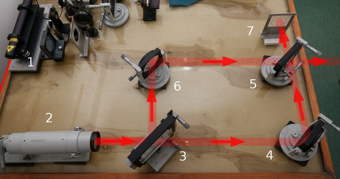
Everything you always wanted to know about the semi-transparent mirror technology (but were afraid to ask) - Test of the Sony A99 mirror
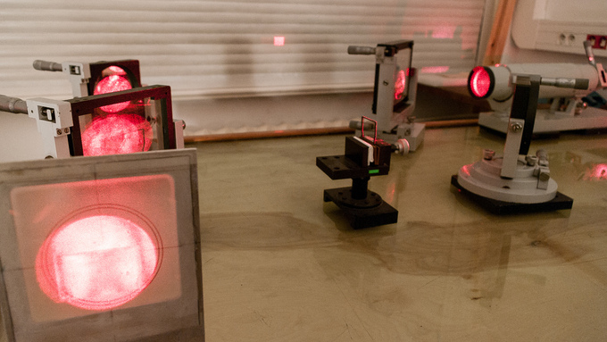
Measurement system: the HeNe laser (1), beam expander (2), beam-splitting mirrors 50:50 (3) and (5), mirrors (4) and (6), screen (7).

The examined mirror was inserted into the optical path between mirrors 5 and 6. Work with a parallel beam eliminates the necessity of using an imaging system as the sample image is created spontaneously on the screen. The second beam leaving the interferometer was used to register the results as both beams carry the same piece of information.

Everything you always wanted to know about the semi-transparent mirror technology (but were afraid to ask) - Test of the Sony A99 mirror
The examined mirror inserted into the optical path

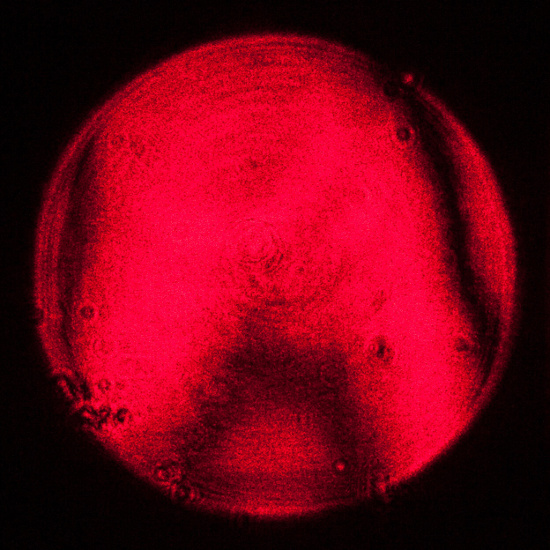
To assess the mirror quality we used a homogeneous field by positioning the interferometer in such a way so the beams from mirrors (4) and (6) overlapped each other perfectly. The field we got is not completely homogeneous because the parts of the system aren’t perfect. A homogeneous field is very sensitive to disturbances of wavefront. The animation shown below presents the reaction of the interferometer when you insert a hand into the system.

Everything you always wanted to know about the semi-transparent mirror technology (but were afraid to ask) - Test of the Sony A99 mirror

You can notice convection currents of warmer air floating above.

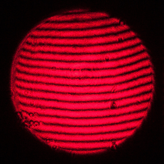
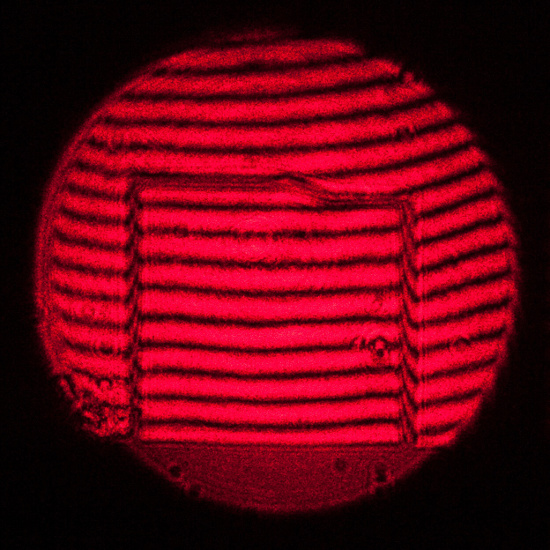
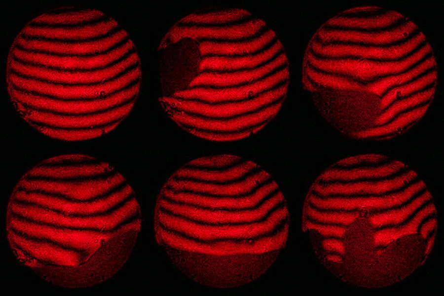
The quantity measurement is easier to carry when you deal with a homogeneous fringes. In order to create the pattern on the output of the interferometer it’s enough you tilt one of the mirrors (6) or (4) vertically or horizontally. The mirrors were tilted by about 2 µm or 0.00002 cm just to show the scale. The mirror was examined for both vertical and horizontal stripes. The reaction of the stripped area to the inserted hand is shown in the next animation.
Everything you always wanted to know about the semi-transparent mirror technology (but were afraid to ask) - Test of the Sony A99 mirror

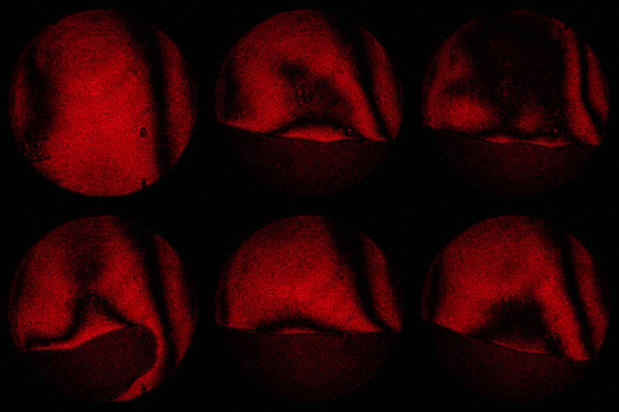
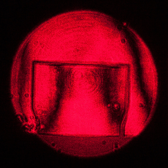
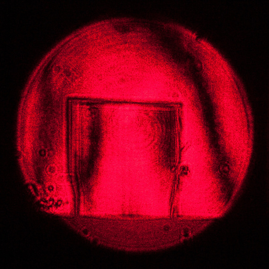
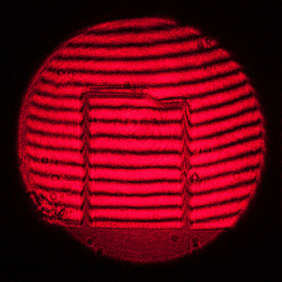
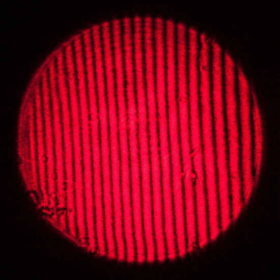
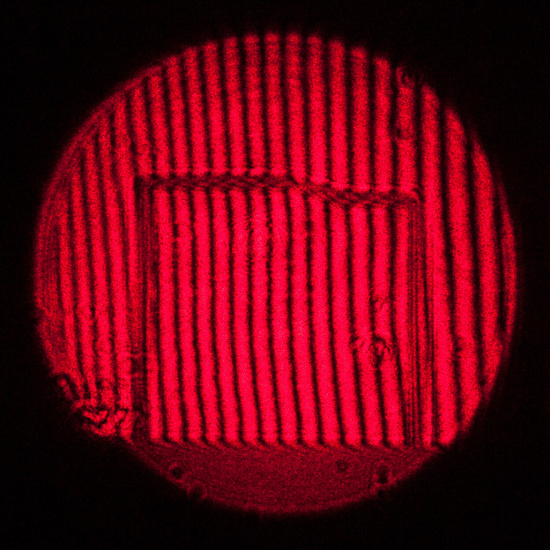
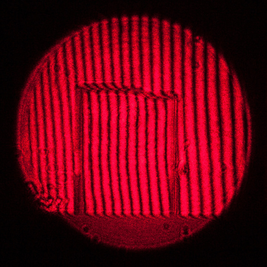
The images below were registered for respectively an empty interferometer, a mirror inserted almost perpendicularly and at an angle of 45 degrees. Inserting a mirror in a perfectly perpendicular position would create serious problems and many new sets of fringes.

Homogeneous field

Everything you always wanted to know about the semi-transparent mirror technology (but were afraid to ask) - Test of the Sony A99 mirror

Everything you always wanted to know about the semi-transparent mirror technology (but were afraid to ask) - Test of the Sony A99 mirror

Everything you always wanted to know about the semi-transparent mirror technology (but were afraid to ask) - Test of the Sony A99 mirror

The mirror cause a slight phase shift. Even if you don’t know its exact thickness and average refraction index you see that inside the outline of the mirror there are just 2 fringes. Taking into account the shape of fringes of the empty interferometer you can conclude that the wavefront disturbance due to the mirror doesn’t exceed one wavelength.

Fringed field (horizontal)

Everything you always wanted to know about the semi-transparent mirror technology (but were afraid to ask) - Test of the Sony A99 mirror

Everything you always wanted to know about the semi-transparent mirror technology (but were afraid to ask) - Test of the Sony A99 mirror

Everything you always wanted to know about the semi-transparent mirror technology (but were afraid to ask) - Test of the Sony A99 mirror

The change of mutual position and shape of the fringes amounts to ¼ of wavelength.

Fringed field (vertical)

Everything you always wanted to know about the semi-transparent mirror technology (but were afraid to ask) - Test of the Sony A99 mirror

Everything you always wanted to know about the semi-transparent mirror technology (but were afraid to ask) - Test of the Sony A99 mirror

Everything you always wanted to know about the semi-transparent mirror technology (but were afraid to ask) - Test of the Sony A99 mirror

The change of mutual position and shape of the fringes amounts to ½ of wavelength.

The mirror introduces small disturbance of the wavefront – about ¼ - ½ of wavelength. Because of that a fast lens might be not limited by diffraction…if it was limited previously at all. It may be still significant if you can find a lens faster than f/2.8 and with a resolution higher than 200 lp/mm. As there are no local disturbances (high-frequency) f/2.8 lenses and slower won’t lose their resolution in a noticeable or even measurable way.