Polarizing filters test
3. Test procedure
One filter of a smaller, 67 mm diameter, also took part in the test. It was Fomei Digital CPL model that doesn’t occur in larger diameters. During the tests we needed to use a special reduction ring to put the filters on our reference lens, then. As a result of that we weren’t able to correctly measure vignetting it introduces. However to place the polarizer in the overall ranking we took an arithmetic mean of other filters’ vignetting for it.
We conducted the photographic tests using Pentax K20D along with the Sigma 17-70 mm f/2.8-4.5 DC Macro lens.
Please Support UsIf you enjoy our reviews and articles, and you want us to continue our work please, support our website by donating through PayPal. The funds are going to be used for paying our editorial team, renting servers, and equipping our testing studio; only that way we will be able to continue providing you interesting content for free. |
- - - - - - - - - - - - - - - - - - - - - - - - - - - - - - - - - - - - - - - - - - - - - - - -
Polarizing filters were rated in five different categories. The way of testing and the score in each of the categories are specified below.
Light transmission and extinction coefficient
The extinction coefficient is a quantity which says how good a polarizer is. It’s defined as a ratio of the intensity of light passing through crossed polarizers to the amount of light passing through parallel polarizers. This parameter is equal to zero for ideal polarizers, about 1/10000-1/200000 for crystal polarizers, and roughly 1/100-1/5000 for foil ones. The extinction coefficient is very convenient for interpretation, as it means how many times less light passes when we cross polarizers.
The extinction coefficient depends on the wavelength. It is cause by the fact that materials like glass and polymers are not perfectly transparent in the whole spectrum, and in the case of foil polarizers the density of “wires”, their length, the thickness of the foil and so on are important. For these reasons it’s good to examine the transmission of the wave polarized parallelly and perpendicularly to the azimuth of the polarizer. In this case, the extinction coefficient is an indirect result that is created by dividing the transmission plots by each other.
To determine the transmission of polarizers we used a halogen light source (Ocean Optics HL-2000) with a multimode fiber SMA of 200 µm core diameter as an illuminator, a microscope 10/160 lens as a collimator, Glan-Thomson polarizer as a reference and an Ocean Optics USB-4000 spectrometer.
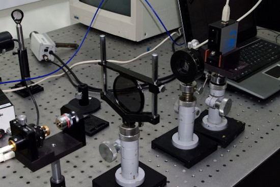 |
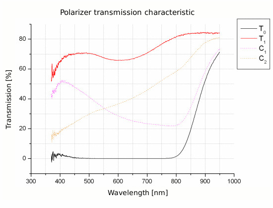
The test set allowed defining the transmission values.
- T0 – corresponds to transmission values of crossed polarizers
- T1 – corresponds to transmission values of parallel polarizers
 |
On the basis of transmission measurements we could determine the coefficient of extinction. In this case the spectrum was divided into three parts:
- B (blue) – 380-495 nm
- G (green) – 495-570 nm
- R (red) – 570-780 nm
| |
|
The values of transmission T0 and T1 obtained through measurements have been averaged in order to determine a mean value of transmission. An ideal polarizer should get results equal to 50%. Scores for the mean transmission have been given in proportion from 0 to 3 for the range of transmission of 25-50%.
In this category, then, a polarizing filter could receive 15 points maximum.
Flares
As a filter is a glass element influencing the behavior of the lens, we tested how the given filter influences reflections and flares when shooting against bright light.
To check the filter’s susceptibility to flares we’ve photographed in the open air at night with a light source placed in the corner of the frame. The scenes have been photographed using a Pentax K20D camera with a Sigma 17-70 mm f/2.8-4.5 DC Macro lens set at 17 mm.
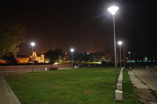 |
Points in this category have been given using an academic scale from 2 to 5, where 5 means a picture with no flares comparing with one without a filter; and 2 means a very strong image degradation. Additionally, the grades were given weight of 1.5, thus the maximum score of 7.5 points in this category.
Scattering
Scattering is rarely tested in optical components, as they are usually made of already well-tested glass, but circular polarizers consist of two layers of foil, glue and, most frequently, an optical flat made of optical glass. Scattering may occur even on glue.
Each filter was light by an ordinary 60W light bulb, set a meter away at a small angle. Then a picture was taken with the following exposure parameters: ISO 100, f=70 mm, 6 secs, f/4.5.
Pictures were imported to the Matlab 7 ® numerical calculations environment in the form of 3D matrices. Each unit consisted of 8-bit information on the intensity of light reaching the sensor at given exposure conditions. The value of intensity (R) has been averaged with a circle of 222 pixels radius in the center of the filter, and with 3 chromatic components (RGB).
We’ve accepted the following score criteria:
- R<15 - 5 pts
- R>150 - 0 pts
Vignetting
Foil polarizers work on the basis of absorption. Light coming from the edge of the field of view goes through the longest optical distance in the polarizer, so according to the Beer-Lambert law T=(1-R)exp(-a*d) the transmission will be smaller. Slight increasing of vignetting is therefore a natural occurrence.
Within the framework of the tests we have taken pictures of a uniformly lit surface using the test kit with and without a filter. Vignetting introduced by the polarizing filter was determined by defining the difference in edge darkening between the two pictures, which was measured by the Imatest software.
We’ve accepted the following grade criteria:
- Worsening the vignetting from 0 to 1% - 5 pts
- Worsening the vignetting by more than 8% - 0 pts
Homogeneity
Homogeneity is a qualitative parameter consisting of the bubble content in the glass and streakiness of the glass. While you can always reclaim an element with air bubbles in it, it’s harder to show streakiness to the sales clerk. This aberration occurs when the surface is uneven or the components of glass (foils) are badly mixed. Light refracts and, as a result , the resolution of images decreases. Precise measurements require so-called shading method, but in the case of filters there’s no need to for this much precision (using shading method you can detect convection of warm air over a hand!)
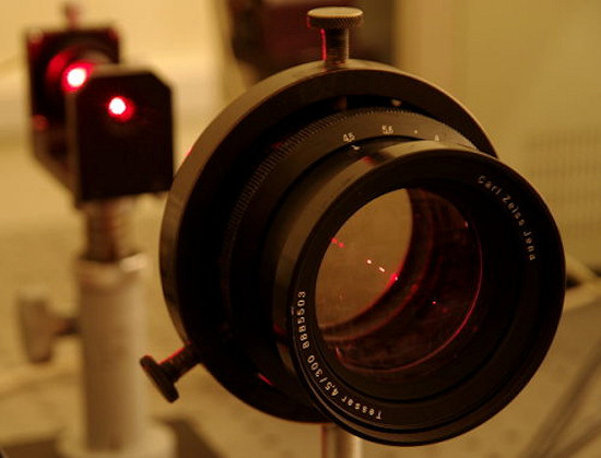
To determine homogeneity each filter was inserted in a parallel beam of light.
 |
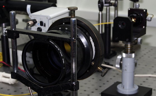 |
Next, a picture was taken from 2.2 m distance.
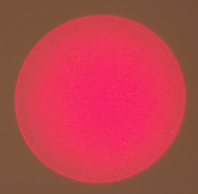 |
A grade in this category was given in academic scale from 2 to 5, where 5 corresponds to unchanged field, and 2 strong deformations.
Final score
The final score is a sum of grades obtained in individual categories rounded off to the first decimal place. The maximum score a filter could get in our test equals 37.5 points.


