Polarizing filters test
2. About light and polarization
Electromagnetic wave – a quick summary for the curious
Light is something so ordinary for us that we don’t usually think about its complex nature. When we see a colorful spill of oil on a puddle, a soap bubble, a CD or we mount a polarizing filter on a lens, it shows its wave character in all its glory.
The most often case is propagation of light in a vacuum. The description is simple in regard to deriving a formula and doesn’t differ much from the propagation of light in air (the refractive index of air is around 1.0003). There’s no need to convince anybody of the existence of magnetic and electric field; nearly everyone played with magnets and amber in their childhood. It turns out that these fields are interchangeable and united by induction laws (see e.g. a transformer). At this point we are reaching Maxwell’s equations which define these fields.

There are no electric charges and no electric current in a vacuum.
Please Support UsIf you enjoy our reviews and articles, and you want us to continue our work please, support our website by donating through PayPal. The funds are going to be used for paying our editorial team, renting servers, and equipping our testing studio; only that way we will be able to continue providing you interesting content for free. |
- - - - - - - - - - - - - - - - - - - - - - - - - - - - - - - - - - - - - - - - - - - - - - - -
The first of the equations should be read like this: changes in the electric induction field D and electric current cause eddy magnetic field H.
The second one describes an opposite situation, i.e. varying-in-time magnetic induction field B is the cause of eddy electric field E. The minus sign is necessary, otherwise an electromagnetic wave would increase in time and this contradicts the conservation of energy principle (something from nothing). It is a known natural principle of contradiction, in this case the changes in one field are prevented by another, over and over again.
The source of an electric field is a charge. In a vacuum both field types have no source. Light doesn’t require a material medium for propagation, field force lines are in this case closed – they have no beginning and no ending.
Field intensity and induction vectors are linked by material equations. In the case of isotropic media only the lengths of vectors are calibrated.

Material and Maxwell’s equations lead to the wave equation.

An electromagnetic wave can be temporarily imagined as a local vibration of E and H fields. The wave equation form is identical for E and H, so we can remain with E field description only. It is the one responsible for visual sensation. After freezing time we get a known, naive picture, where intensities oscillate on the way of propagation k.
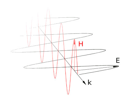
This illustration is useful, although the real distributions of fields in space are a much more complicated matter. From the illustration above we can draw a few conclusions:
- The devil's not so black
- An electromagnetic wave is transverse, i.e. E, H, and k are mutually perpendicular
- Directions of E and H vectors’ vibrations are preserved.
Polarization
Polarization is a complete or partial array of e.g. electric field intensity vector’s vibrations. In the last picture of the previous chapter there’s a wave polarized linearly in the vertical azimuth, which is a trivial case. Why is the azimuth of polarization vertical? It’s a matter of agreement. Historically, the direction of polarization was considered as the direction of a magnetic vector’s vibrations (F. Ratajczyk, Dwojlomnosc i polaryzacja optyczna”, OW PWr W-W 2000). It’s an empirical definition which comes as a result of the polarization of radio waves on wires. In optics we also use the concept of the direction of polarization in accordance with the direction of an electric vector (D. Halliday, R. Resnick, “Podstawy Fizyki 4”, PWN W-wa 2005).
We’re interested in circular foil polarizers. They work on the basis of inducing electric current in conductors made of macromolecules saturated with appropriate particles (charges source). The arranging of the molecules is accomplished through pulling out the foil in one direction.
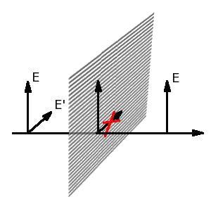
In the above picture you can see the principle of operation of foil polarizers (or wire ones e.g. for microwaves). If we consider a wave whose electric field vibrates like the E vector, it will pass through the polarizer not being suppressed by it. In the case of a field oriented like the E’ it will cause a movement of charges in conductors and lose up its energy on them.
Crystal polarizers work differently.
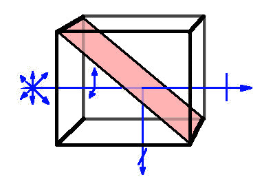
They’re made of linearly birefringent crystal, one in which waves that are linearly polarized in a defined direction and mutually perpendicular can propagate. What’s more, these waves move at different speeds, so the index of refraction depends on the direction. The concept of slow and fast waves is introduced here. In the case of Glan or Glan-Thompson polarizer (glued with blackened walls version) we deal with two prisms put together in a way that the fast vector in one agrees with the slow one in the other. The wave called extraordinary will go through, while the ordinary one, with regard to the chosen refractive indexes, will undergo total internal reflection.
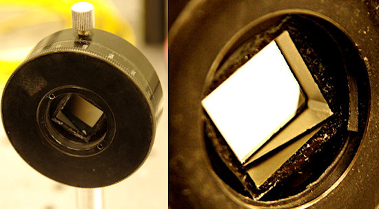 |
Crystal polarizers are usually made of calcite, and their working range is around 350-2700 nm. Their only fault is small dimensions (on sale up to 15 mm) and small angles of light entering (15 degrees maximally).
Circular polarizer
As we’ve already mentioned, in a linearly birefringent medium there are only these two perpendicularly polarized waves, called eigenwaves (eigenvectors). Let’s imagine we enter the light polarized linearly at an angle of 45 degrees to the eigenvectors of the medium (on the left, rear of the graph).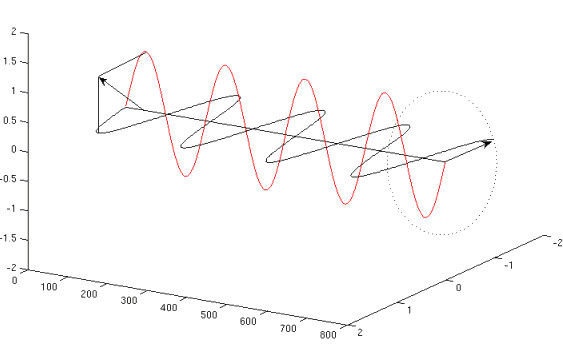
The electric vector is projected on two possible polarization directions and in a birefringent medium the fast wave (electric vector marked by the black sinusoid) and the slow wave (red sinusoid) are propagating. When we look at the graph the fast wave slowly overtakes the slow one and at the output the difference of paths equals in this case 1/4 of the wavelength (difference of phases of 90 degrees). When the wave leaves the medium there exist any directions of the electric vector vibrations, so the eigenvectors are merged into a single photon. Now, however, they cannot be set for linear polarization, because the maximum intensity of one wave’s electric field corresponds to the minimum of the other. Once we trace the further course of the sinusoids, however, it turns out that the resultant electric vector plots a helix (here it’s right-handed). If the difference of the phases equals 90 degrees, the projection of the helix on a plane perpendicular to the movement is a circle. If the difference is not 0, 90, 180… we obtain the elliptical polarization.
As we can see, if we want to obtain a circular polarizer, all we need to do is to put together a linear polarizer and a plate retarding the eigenvectors phase by 90 degrees (so- called quarter-wave plate), set at an angle of 45 degrees. Obviously, the quarter-wave plate introduces the given difference of phrases only for one wavelength, in other parts of the spectrum the difference will be slightly distinct, so the whole polarizer will be elliptical. For the quarter-wave plate to be sensitive the least for the wavelength changes (quite flat curve of dispersion), it needs to be of zeroth order, exactly the same as illustrated on the graph above. The difference of phases equaling 90 degrees can be executed like on the graph below.
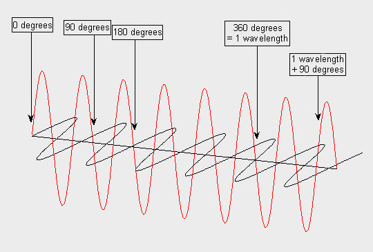
We can see a quarter-wave plate of the first order here. As we can see, if we slightly change the wavelength this tiny difference will be magnified many times and, eventually, the plate will display strong dispersion. This is very inconvenient, as you can easily imagine that e.g. for a green color we have a circular polarizer, and for blue and red a linear one.
Dispersion of the quarter-wave plate and the range of a linear polarizer’s work you can observe yourself, all you have to do is put it on a reflecting surface, thread up and then down.
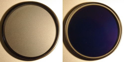 |
What happens? If we put the filter thread up, the light passes though the quarter-wave plate and comes out of it unpolarized. Then, it goes through the polarizer, reflects off surface underneath, goes through the polarizer once more (the azimuth hasn’t changed when reflecting), passes through the quarter-wave plate and we can observe light polarized circularly. In this second case the light firstly passes through the linear polarizer, then the quarter-wave plate. After reflecting off the surface underneath the filter the state of polarization changes its helicity (e.g. from the right- to left-handed). Light of opposite helicity vanishes on a circular polarizer. If it were ideal, we should see nothing, but the field under the polarizer is navy blue. As a result of this we can see that for violet the linear polarizer stops working and the quarter-wave plate contributes to the phase retardation larger than 90 degrees.
This phenomenon was broadly used in optical disc players (laser), so that the light doesn’t come back to the laser but, after reflecting off the disc, hit only the detector (optical isolator form).
The order of a quarter-wave plate is easily determined using the spectrum of light passing in the opposite direction than when examining the extinction coefficient. This method has been introduced by prof. F. Ratajczyk (“Dwojlomnosc i polaryzacja optyczna” OW PWr W-w 2000). The spectrum without the minima of transmission, i.e. without spectral stripes originates when we deal with a zeroth order quarter-wave plate. The course of this measurement will be explained in the next chapter.
We can also observe the effect connected with angular dependency of phase retardation of a quarter-wave plate.
 |
The first picture: we’re looking from the thread side. The second, from the second side. The third, if we additionally tilt the filter. If we can observe effects like these in the light reflected behind the filter, we deal with a circular polarizer.
Why not a linear polarizer?
Of course it’d be easier. Once, there was no need to use circular polarizers, as cameras weren’t equipped with autofocus and TTL metering. What’s the meaning of this?
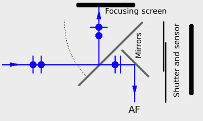
The main mirror of modern DSLRs is partly transparent. When we imagine a reflected and refracted ray (entering the mirror), electric field needs to be separated into these two directions. If the reflected and refracted rays go at an angle of 90 degrees against each other, the projection of the E vector on the direction of the reflected ray will be zero, which means that the light will be entirely polarized. When this situation occurs, we say that the light falls on the boundary at Brewster’s angle. The full polarization occurs only, when we deal with dielectric surface (glass, water and other isolators), whereas a mirror in DSLRs is mostly partly metalized. Apart from that, Brewster’s angle for most glasses is around 50-60 degrees, whilst a semi-transparent mirror is tilted at an angle of 45 degrees (rays from the lens also come at different angles). This slightly improves the situation, but light is partially polarized.
Consequences
If we were to use a linear polarizer for taking pictures and put it in a way that the light enters at a vertical vector direction E, light metering (behind the focusing screen) will indicate a too small reading and the picture will definitely be overexposed. If we set the polarizer to allow the light waves of horizontal vector E, autofocus will refuse to work with regard to too little light amount.
In reality there are also some other effects appearing, for example dependence of sensor’s sensitivity and AF sensors on polarization.
The solutions to the above gripes are circular polarizers, which “simulate” the unpolarized light in a way that the horizontal and vertical constituents have the same intensity (there’s no privileged direction). Thanks to that, no matter what the polarizer’s azimuth on the lens is, the same amount of light reaches the sensors.


